A brief introduction to DIN sockets on hifi
I regularly mess with all kinds of vintage hifi and audio stuff, but I have a particular soft spot for compact cassette decks and tape recorders, and a side effect of this fondness is that I'm somewhat frustrated by RCA cables. To put it bluntly, stereo RCA cables in their "modern" form are a blatant bodge. The plug can only carry one signal channel (since it was designed before the rise of stereo), so let's just use two of them. Yeah, maybe, if you're putting something together quickly for a tech demo, but this solution adds a lot of unnecessary complication to hooking up tape recorders in the form of a frankly ridiculous number of wires and plugs1.
An alternative solution in the form of the the DIN connector2 has existed and was widely used in Europe for a while, but it has now faded into relative obscurity. This means there's not a lot of information about it on the internet and when I tried using DIN cables myself I ran into some unexpected quirks. This page will hopefully save you the trouble of having to figure this out for yourself.
Pinout
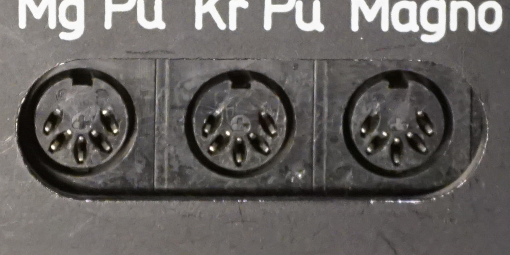
The diagram below shows the usual pinout used by amplifier tape sockets. Sockets for playback only equipment (tuners, record players) will generally use the same pinout with the "rec out" pins unconnected.
1: rec out left 4: rec out right 2: ground 5: playback in right 3: playback in left
The cables connect each pin to the same pin on the other end, so the socket on a tape deck will have a mirror image of this layout, the output is connected to pins 3,5 and pins 1,4 are used for input3. This has the side effect that you can't use an ordinary DIN cable to connect something like a tuner directly to a tape deck, but since that's unwise for reasons I'll get to later, this might be an intentional feature.
One thing to note is that while hifi equipment generally used this pinout, there wasn't an actual standard set down for this and other audio devices like portable tape recorders could very well use a different pinout or use some of the pins for proprietary control signals. When in doubt its best to consult a manual or schematic if possible before plugging anything anywhere.
Cables
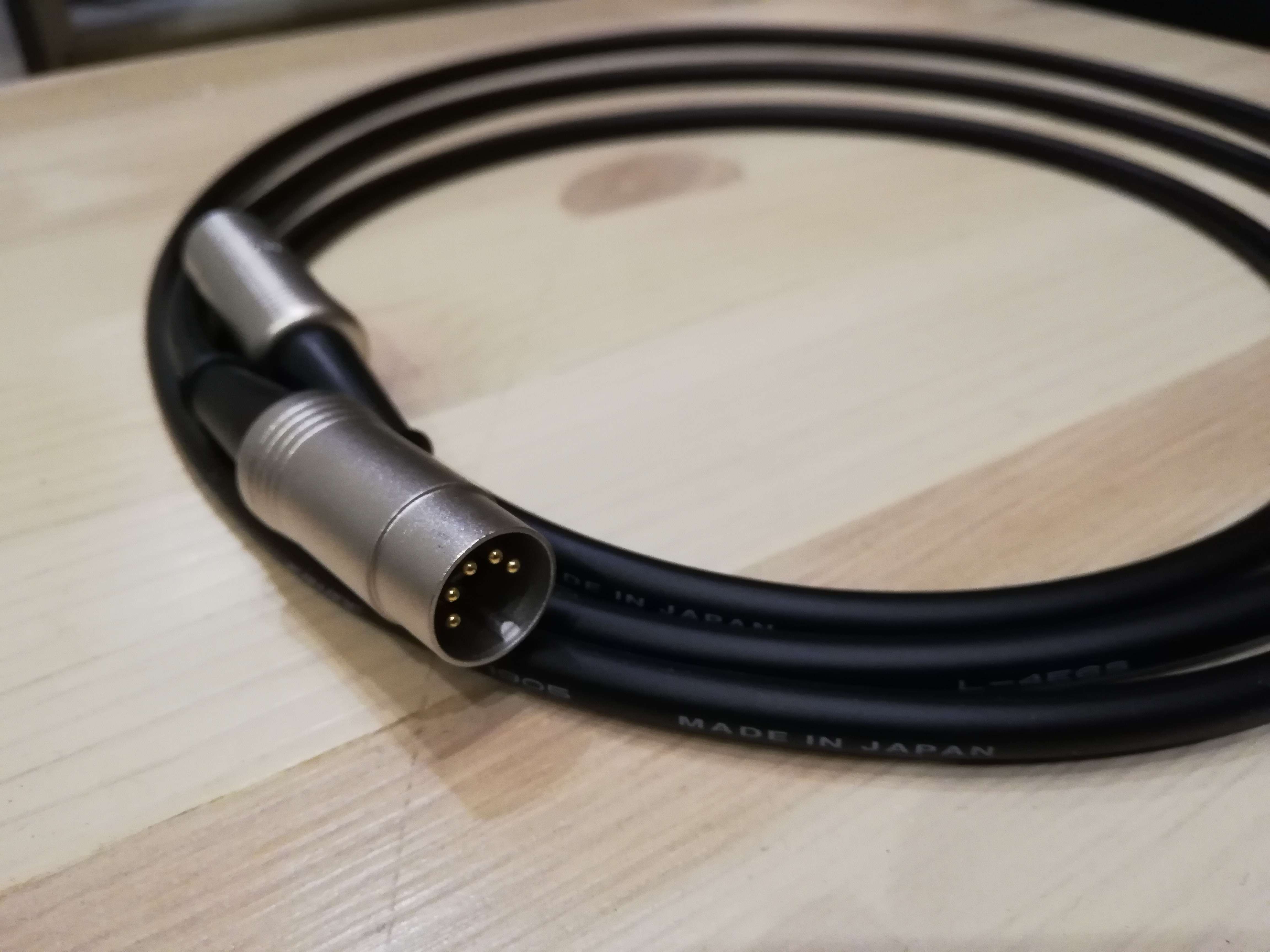
One difficulty in using DIN sockets on your equipment is that DIN interconnects aren't made anymore. There are plenty of cables around to connect a DIN socket to something else, usually RCA or an audio jack, but cables with DIN plugs on both ends seem to be made only as MIDI interconnects. MIDI doesn't use all 5 pins, therefore these cables often don't have all pins wired. As such, you either have to find used cables or make your own from scratch. I chose the second option, because is one of the rare cases of a home-made cable being much higher quality than anything I could buy.
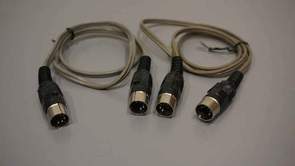
Making your own cables also eliminates wiring headaches you could run into with second-hand cables. I have some old, home-made cables (courtesy of my parents' garage) with only the playback pins wired up and one of them has its connections crossed. I have no idea why or if such cables were ever sold commercially and if there was any standard in place for marking how a particular cable is wired. The only advice I can give (again) is that you should probably check the wiring of any cables you encounter in the wild before plugging them into anything.
Levels
The final oddity of DIN connections has to do with sensitivity. Due to the abovementioned lack of a standard, different manufacturers often use somewhat inconsistent levels to begin with, but for the most part output level on hifi equipment will be in the same ballpark as line level. Thus, a DIN input on most amlifiers will generally work with line level signal, but this doesn't apply to cassette recorders as the DIN input on those is a lot more sensitive4, usually taking signals as low as 1-10mV (but I've even seen 0.1 mV on a spec sheet). For some comparison this is about the same as phono or microphone inputs, in fact DIN inputs are internally often wired to the microphone preamp in cassette recorders, even those that have RCA line level inputs alongside the DIN socket.
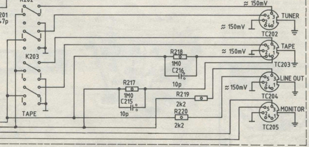
This of course means an ordinary DIN (or line level) signal would overdrive this input by a lot, even at low volume, so on amplifiers the DIN outpus are usually connected through a high value resistor. This arrangement of attenuating and then amplifying seems like a good recipe for all kinds of noise to happen, but it seems to work all right in practice. It does cause problems with feedback from the output, so tape decks usually mute the DIN output during recording. This makes DIN cables less than ideal for three head tape decks as it blocks you from using the monitoring feature commonly found on them.
1: Separate connectors for the left and right channels can be useful for some creative tricks in a home studio, but not so much for listening or recording off the radio.↑
2: The standard itself specifies an entire family of connectors with different pin layouts and numbers and the five-pin variant I'm going to call "the DIN connector" for the rest of this page was used for a wide variety of purposes, most notably MIDI devices and IBM PC keyboards.↑
3: Note that the pins aren't numbered in what would seem like the logical order. Apparently it was important to keep consistency with the numbering of 3-pin plugs used on some mono equipment.↑
4: To some extent this is also the case with line level, RCA inputs on tape decks are often more sensitive than those on amplifiers as this lets tape recorders deal with low signal leves coming from a tuner set to a distant radio station for example. What makes DIN sockets unusual is the magnitude of this difference↑